

CHAPTER 12: TAILINGS STORAGE FACILITY
Tailings Storage Facility (TSF) dam constructions are often an essential part of mining projects.
This chapter covers principal general terms, techniques, and materials in dam construction and is a compliment to the information about TSFs in chapter 4. It aims to give a more in-depth view of dam types, material properties, subsoil stability, potential problem areas and analysis and control methods to mitigate, as well as give ideas on further reading on the subject.
Dam construction
Generally, the three main functions of a dam are as follows: A dam is a construction to constrain and store water and/or material. It has a water outlet and a spillway to be able to safely control the dam water level and avoid uncontrolled overflow. Many dam constructions rely on gravity, the weight of the dam construction material provides the force that holds the content of the dam in place. Water dams are non-permeable to constrain water. However, TSFs are semi-permeable, embankment dams, constructed to allow a controlled seepage. Seepage collected in the dam drain and outlet water from a TSF is usually collected in a sedimentation pond. Before release into the downstream recipient, the water is analysed and may be treated to avoid risk of environmental pollution or harm to potable water resources downstream.
Principal dam design elements
Principal elements in dam design may vary depending on dam purpose, characteristics, and quantities of tailings to be deposited, and the properties and amount of material available for the dam construction. An embankment TSF dam may contain the following technical components (Figure 2).
- Foundation (the stable base upon a dam is erected)
- Core (or membrane, constrains water upstream of the dam)
- Shell (constrains the stored tailings within the dam)
- Transition Filter (keeping core material in place, ensuring core function over time)
- Internal Drain (collecting seepage, reducing amount of water within the downstream dam shell, ensuring shell stability)
- Toe Drain (collecting seepage, reducing amount of water within the downstream dam toe to ensure toe stability)
- Rip-rap (erosion protection of the shell surface against waves or running water)

Figure 2. Schematic figure of a dam construction.
TSF dams are commonly enlarged and extended over time. There are three principal ways to increase the TSF capacity: to raise the dam upstream, downstream and centerline. Each of these concepts have benefits and disadvantages. Upstream raise requires the least amount of dam construction material, but each raise inward will decrease available tailings storage volume. Downstream raise will increase the tailings storage volume with each extension, occupy a much larger land area and require increasingly large volumes of dam building material (Figure 3).

Figure 3. Enlargements of tailings dams (1: downstream, 2: upstream and 3: centerline).
Designing a dam construction
Tailings dams are generally embankment dams, constructed by the use of aggregates and soil locally available. In many cases suitable waste rock fractions and excavated soil material can be made available from the mining operation itself. It is not uncommon that dedicated day-pits are opened to provide material with required characteristics suitable for building specific elements in a dam construction project (e.g., dam core).
Stability and erosion
Coarse, heavy materials can withstand erosional forces of water and wind, but fine-grained materials may be more prone to erosion and get washed out by heavy rain or blown away from the surface of a dry beach in a TSF. The properties of a granular material with different water content may be described by the analogue of building a sandcastle on a beach. The sandcastle only stands if the water content is within the right interval. When the water content in the pore spaces is too low, you may create a wall, but the grains will crumble. If the water content is too high, or if the material is completely dry, it will be impossible to even erect a sandcastle wall in the first place. Very fine grain sizes such as clay and silt have very different material properties compared so sand and coarser materials. Due to their small particle size, the physical cohesion forces are much stronger. This is why clay and silt sometimes form vertical walls that can be stable over time. But also in this case, the water content is crucial. If the water content however is too high, fine-grained material may turn instable and will be prone to plastic deformation, likely to cause slumps and landslides.
Use of specific materials in dam construction elements
Silty materials are generally avoided in dam constructions due to their poor technical characteristics (potentially instable, risk for liquefaction). Silty, clayey layers in the subsoil are also undesirable, as silt content may affect costs related to dam foundation and dam design to mitigate future dam stability risks. Depending on host rock, mining tailings may contain considerable quantities of silt. This must be reflected when designing and operating a TSF. The dam foundation usually consists of rock or earth and supports the dam embankment construction, providing stability for vertical and horizontal loads. Permeable layers in the foundation, even if not exposed at the surface, may represent a risk to dam stability (seepage beneath the dam) and are undesired in a dam foundation. Depending on setting, a dam foundation may be built as a part of the dam construction replacing unfit soil with suitable materials or technical elements. Fine-grained materials (clay) are used in near-non-permeable layers such as the dam core or dam membrane. Sandy materials are commonly used as filter materials. Coarse-grained materials are used in dam shells, foundations, for drainage (internal, toe drains, and stability in dam constructions.
Foundation stability – Subsoil properties
It is very important to know the characteristics of soil or granular materials intended for use as dam foundation or as building material to construct different elements of a dam. Another important issue is to investigate the stratigraphy, layers and materials present in subsoil at an intended dam construction site. For instance, a clay-rich lateritic subsoil is not appropriate in a dam foundation. A number of investigation methods are available to properly assess material properties and perform soil mechanics geotechnical calculations. Standardized sampling and investigation routines are available to avoid potential mistakes that could affect the quality of subsequent analysis results.
Investigation methods
- Excavation of a soil pit to map shallow layers and sample material.
- Mapping of soil or rock by drilling, collecting sediment or rock drill cores for material sampling and geotechnical analysis.
- Geophysical methods - geomagnetic, seismic, electromagnetics. Often used in combination with a drill programme to verify the results.
- Remote sensing - laser scanning or interferometric synthetic aperture radar (InSAR)
Analysis methods
- Grain size and grain distribution analysis, lab test of field samples. Required sample size increases rapidly with grain size of the sampled material.
- Cone penetration test (CPT)is a common method to assess geotechnical properties of soil and sediment. A rod with a cone tip is pushed into the material while measuring penetration rate, rod mantle friction and generated pore water pressure at the tip. Often used in combination with grain size analysis.
- Chemical analysis, lab test of collected field samples may be relevant in certain geological settings. Some materials, e.g., sulphide bearing soil or rock may not be suitable for use in construction due to increased acid drainage.
- Shear strength analysis, lab test of soil or sediment samples to assess material strength when stressed.
- Computer visualisation and modelling of available data such as geological mapping, field measurements and analysis results.
Dam failure – common reasons
A TSF failure could possibly result in catastrophic events such as downstream mass flow and flash flood, as well as potential pollution of large area and loss of human lives. Common reasons for dam failures include:
- Dam fill volume exceeds capacity of planned dam design, leading to construction failure.
- Tailings material technical properties/distribution/fill operation in the dam fill are not in line with originally planned dam design.
- Dam design or foundation is not appropriate to withstand external impact, such as earthquake risk (if relevant) of the region.
- Episodic drought/heavy precipitation, flash flood in the upstream catchment.
- Technical failure or malfunction of dam elements or equipment (dam core, dam outlet, monitoring or emergency equipment, emergency spillway).
- Improper subsoil investigations before dam construction or enlargement.
- Improper design to upgrade/enlarge existing dam constructions to facilitate storage of a larger waste volume or change of dam technical design.
- Poor monitoring & quality control during dam construction, operations, reclamation or decommission, not detecting potential risks in time.
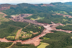
Figure 4. Dam failure at Brumadinho, Brazil, 2019.
Mitigation of risk and consequences of dam failure:
TSF failure risk may be mitigated by appropriate planning to ensure that the dam has capacity to hold a relevant additional safety volume, in combination with proper safety measures such as emergency spillways. Physical properties of the dam construction material, subsoil material and tailings material contained within the dam is equally important. The subsoil should be investigated to ascertain there are no hidden deeper layers that may impair its use as stable foundation for a dam construction. Material characteristics and behaviour may in some cases change greatly when affected by vibrations or high pore pressures. Elevated pore water pressure within a dam construction or high-water level in the downstream dam shell will usually lower the dam stability and indicate an increased potential failure risk. As friction between particles is lowered, the ability of the dam design to hold upstream tailings and water safely in place diminish. If the TSF-material is water-saturated and most pores are waterlogged, the pore pressure will rise. If the pores are filled with air/gas the pore pressure will sink.
If proper dam construction, operations and monitoring is in place, the operator may identify and react properly if any changes in seepage and/or dam wall surface appears. Piping may often be identified by discrete seepage at the dam toe, or sinkholes on the dam top or side. Dam safety assessment is a continuous and iterative activity including:
- Long-term planning of mining and tailings dam operation allowing timely forecast of necessary upgrades or (climate)changes affecting the dam or its catchment.
- Regular training and education of workforce competency.
- Ensure of proper dam design suitable for operations and tailings type is in place, and that the dam foundation design is based on subsoil investigations.
- Ensure proper permission / concession / environmental impact assessment process.
- Ensure proper planning, continuous monitoring and control of operations is in place. Continuous records of measurements and analysis results shall be available. Anomalies shall be addressed and investigated.
- Regular control by authorities to ensure that operations is in line with relevant permissions, that monitoring programs and safety measures are in place and running.
- Ensure safety equipment, dam outlet and emergency spillway are maintained and operational.
- Ensure reclamation plans will not affect the TSF’s ability to maintain safe storage (e.g., tree roots protruding into the dam core, creating pathways for seepage).
- Identification of seepage occurrence and change (location, amount), recognise changes in dam face topography / adjacent land surface (settling/subsidence, bulge, cracks).
- Regular analysis of water released from a TSF sedimentation pond (e.g., relevant chemical elements, pH, turbidity).
- Monitor and analyse adjacent downstream ground water resources.
Governmental supervision of TSF
Government officials responsible for supervision of a TSF shall maintain contact with the operator and relevant stakeholders such as local/regional municipality administration. Object is to ensure that environmental legislation and standards are followed properly. Authorities, together with TSF operator and relevant stakeholders, are to assess and evaluate potential risk scenarios related to the site (type of tailings, size and topography of upstream water catchment, downstream land use/settlements/protected areas, potential impact of dam failure). Commonly, the TSF operator and relevant authorities schedule meetings on a regular basis to discuss operation and supervision. If there is an incident, this should regardless of severity immediately be reported to relevant authorities, including mitigation actions. In the subsequent incident follow-up, actions taken and preventive measures to avoid reoccurrence shall be presented.
Monitoring, inspections, and instrumentation of tailings dams
Monitoring of TSFs must be conducted on a day-to-day basis to minimize and detect the risks for dam failures because of i.e., slope failures, sliding settlements of tailings for upstream construction, earthquakes – liquefaction and erosion (internal and external). Parameters to measure are seepage, displacements (surface, internal), pore pressure, total stress (cracking potential), water quality (turbidity, internal erosion).
Seepage controls are conducted to quantify water discharge passing through the dam, to evaluate the effectiveness of the impervious zone of the dam, estimate the relationship between seepage and reservoir head and to have long term trends in seepage over time. The seepage is measured on the downstream side of the dam, whereas the water is collected in one or several points and then conducted through pipes to a measurement chamber at the downstream toe. At the chamber the quantity of seepage is measured by a V-notch (water head above the V-notch, manual/automatic measure by a fixed calibrated scale) (Figure 5.) or by a water-level recorder (automatic measurement).
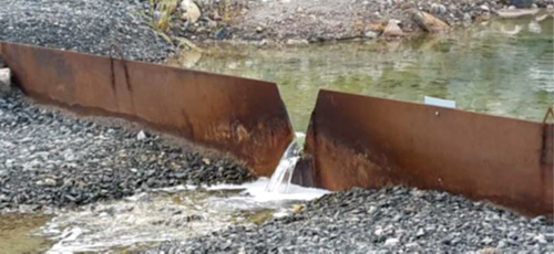
Figure 5: Measurement of water head above the V-notch (manual or automatic).
Surface displacement controls are conducted to verify elevation of the top of the crest/core. Involves a network of markers (geodetic bolts, Figure 6) placed on the surface and in the dam core. The coordinates of the markers are determined by triangulation.
Internal displacement controls are conducted to monitor subsurface movements and deformations including horizontal, vertical, and longitudinal displacements. The aim for the measurements is to detect zones of movement, establish whether movement is constant, accelerating, or responding to remedial measure. It is also important to check whether deformations are within design limits (during construction, during and after impoundment). How to measure: Inclinometers (can be installed horizontal and vertical) and extensometers (longitudinal displacements, installed horizontally and parallel to the dam axis) (Figure 6).
Pore pressure measurements are carried out by pressure instruments installed in boreholes from the ground surface to the desired measurement depth. Regular or continuous pore water pressure and ground water table measurements can detect changes that may indicate seepage or piping. In dam constructions the pore pressure can be used for seepage control and monitoring (Figure 6). Pressure instruments are typically installed in the dam foundation, downstream of the dam or in lateral abutments (dam supports). Instruments used are; Sensors (electronic and pneumatic), Casagrande filter or cell installed inside a plastic tube (manometer or electrical sensor), piezometers (water pressure sensors).
Measuring water quality is conducted to detect early indications of internal erosion within the dam construction. Seepage water that is murky with dispersed soil particles might indicate internal erosion, parameters like turbidity (indicator of very fine-grained suspended sediments), pH and water chemistry (acidic, metal-rich water can indicate oxidation within the construction) are often measured. Measuring the water temperature is to indicate leakage, frozen layers, and is important for evaluation of the total cracking potential. Temperature is measured with i.e., fiber optics and thermo-couples.

Figure 6: Conceptual figure of measurements, instruments, in a dam construction.
Overall, when designing a dam construction, the water pressure (also referred to as hydrostatic pressure), and the permeability (a materials ability to allow fluids and gas to permeate through its pore space) must be accounted for. Permeability is influenced by the distribution, shape and relative amount of connected space (pores) available for transport in the material in question. The upstream pressure, e.g., the height of a free water column or within the pores on the upstream side will also affect the permeability.
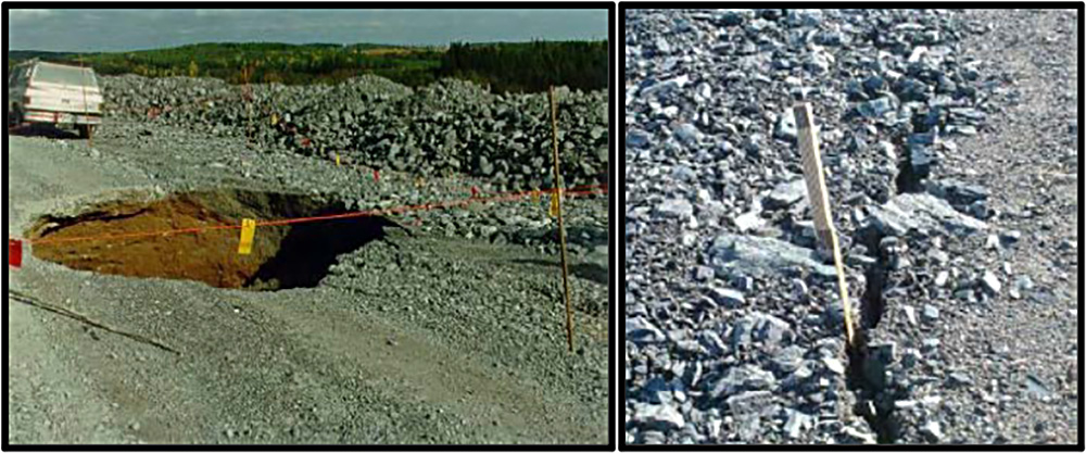
Figure 7: Sinkhole and crack in a dam construction.
Visual inspections
Visual inspections should be a part of the monitoring program and carried out with a checklist. Inspections may include foot patrols on the dams, galleries, and the tunnels. At these places, look for damage or settlements, sinkholes, signs of movement, cracks, and visual leakage and turbidity in the leakage water (Figure 7). Also check on spillways, gates, functions of different equipment, abnormalities in the instrumentation and other abnormalities at site.